LTC3104
3
3104f
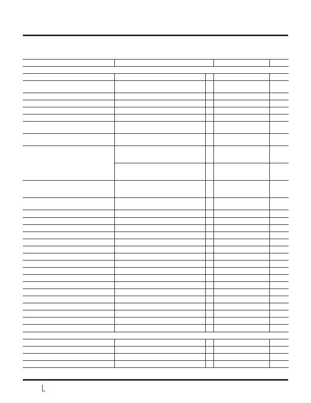
ELECTRICAL CHARACTERISTICS
The l denotes the specifications which apply over the full operating
junction temperature range, otherwise specifications are at T
A
= 25癈 (Note 2). V
IN
= V
INLDO
= 10V unless otherwise noted.
PARAMETER
CONDITIONS
MIN TYP MAX UNITS
Step-Down Converter
Input Voltage Range
l 2.5
15
V
Input Undervoltage Lockout Threshold
V
IN
Rising
V
IN
Rising, T
J
= 0癈 to 85癈 (Note 4)
l
2.1
2.1
2.6
2.5
V
V
Input Undervoltage Lockout Hysteresis
(Note 4)
0.4
V
Feedback Voltage
(Note 5)
l 0.588 0.6 0.612
V
Feedback Voltage Line Regulation
V
IN
= 2.5V to 15V (Note 5)
0.02 0.05
%/V
Feedback Input Current
(Note 5)
l
1 20
nA
Oscillator Frequency
T
J
= 0癈 to 85癈 (Note 4)
l 0.93
1.0
1.2
1.2
1.55
1.45
MHz
MHz
Quiescent Current, V
IN
Active
RUN = V
IN
, RUNLDO = V
IN
, MODE = 0V,
FB > 0.612, Nonswitching
600
礎
Quiescent Current, V
IN
Sleep
T
J
= 0癈 to 85癈, RUN = MODE = V
IN
, FB > 0.612
RUNLDO = V
IN
(Note 4)
RUNLDO = 0V (Note 4)
2.6
1.8
3.3
2.6
礎
礎
RUN = MODE = V
IN
, FB > 0.612
RUNLDO = V
IN
RUNLDO = 0V
l
l
2.8
1.8
5.5
4.5
礎
礎
Quiescent Current, V
IN
Shutdown
RUN = 0V, RUNLDO = 0V, T
J
= 0癈 to 85癈 (Note 4)
RUN = 0V, RUNLDO = 0V
l
1
1
1.7
3.3
礎
礎
N-Channel MOSFET Synchronous Rectifier Leakage
Current
V
IN
= V
SW
=15V, V
RUN
= 0V
0.01 0.3
礎
N-Channel MOSFET Switch Leakage Current
V
IN
=15V, V
SW
= 0V, V
RUN
= 0V
0.01 0.3
礎
N-Channel MOSFET Synchronous Rectifier R
DS(ON)
I
SW
= 200mA
0.85
?/DIV>
N-Channel MOSFET Switch R
DS(ON)
I
SW
= 200mA
0.65
?/DIV>
Peak Current Limit
l
0.40 0.50 0.75
A
PGOOD Threshold
FB Falling, Percentage Below FB
14 10 5
%
PGOOD Hysteresis
Percentage of FB
2
%
PGOOD Voltage Low
I
PGOOD
= 100礎
0.2
V
PGOOD Leakage Current
V
PGOOD
= 5V
0.01 0.3
礎
Maximum Duty Cycle
l 89 92
%
Switch Minimum Off Time (t
OFF(MIN)
)
(Note 4)
65
ns
Synchronous Rectifier Minimum On Time (t
ON(MIN)
) (Note 4)
70
ns
RUN Pin Threshold
RUN Pin Rising
l 0.76 0.8 0.85
V
RUN Pin Hysteresis
0.06
V
RUN Input Current
RUN = 1.2V
l
0.01 0.4
礎
MODE Threshold
l
0.5 0.8 1.2
V
MODE Input Current
MODE = 1.2V
0.1 4
礎
Soft-Start Time
0.7 1.4 2.5
ms
LDO Regulator
LDO Input Voltage Range (V
IN(LDO)
)
l
2.5
15
V
LDO Output Voltage Range (V
LDO
)
I
LDO
= 1mA
l
0.6
14.5
V
LDO Feedback Voltage
l
0.576 0.6 0.624
V
LDO Feedback Input Current
l
1 20
nA
发布紧急采购,3分钟左右您将得到回复。
相关PDF资料
LTC3445EUF#TRPBF
IC REG TRPL BUCK/LINEAR 24-QFN
LTC3446IDE#PBF
IC REG TRPL BCK/LINEAR 14-DFN
LTC3537EUD#TRPBF
IC REG DL BST/LINEAR SYNC 16-QFN
LTC3541EDD#TRPBF
IC REG DL BCK/LINEAR SYNC 10-DFN
LTC3670EDDB#TRPBF
IC REG TRPL BCK/LINEAR 12DFN
LTC3672BEDC-1#TRPBF
IC REG TRPL BCK/LINEAR 8-DFN
LTC3700EMS#TRPBF
IC REG DL BUCK/LINEAR 10MSOP
LTC4151HMS#TRPBF
IC PWR MONITOR MS 80V SD 10MSOP
相关代理商/技术参数
LTC3105
制造商:LINER 制造商全称:Linear Technology 功能描述:400mA Step-Up DC/DC Converter with Maximum Power Point Control and 250mV Start-Up
LTC3105EDD#PBF
功能描述:IC CONV DC/DC 400MA HIEFF 10-DFN RoHS:是 类别:集成电路 (IC) >> PMIC - 稳压器 - 专用型 系列:- 标准包装:43 系列:- 应用:控制器,Intel VR11 输入电压:5 V ~ 12 V 输出数:1 输出电压:0.5 V ~ 1.6 V 工作温度:-40°C ~ 85°C 安装类型:表面贴装 封装/外壳:48-VFQFN 裸露焊盘 供应商设备封装:48-QFN(7x7) 包装:管件
LTC3105EDD#TRPBF
功能描述:IC CONV DC/DC 400MA HIEFF 10-DFN RoHS:是 类别:集成电路 (IC) >> PMIC - 稳压器 - 专用型 系列:- 标准包装:43 系列:- 应用:控制器,Intel VR11 输入电压:5 V ~ 12 V 输出数:1 输出电压:0.5 V ~ 1.6 V 工作温度:-40°C ~ 85°C 安装类型:表面贴装 封装/外壳:48-VFQFN 裸露焊盘 供应商设备封装:48-QFN(7x7) 包装:管件
LTC3105EMS#PBF
功能描述:IC CONV DC/DC STEP DOWN 12-MSOP RoHS:是 类别:集成电路 (IC) >> PMIC - 稳压器 - 专用型 系列:- 标准包装:2,000 系列:- 应用:控制器,DSP 输入电压:4.5 V ~ 25 V 输出数:2 输出电压:最低可调至 1.2V 工作温度:-40°C ~ 85°C 安装类型:表面贴装 封装/外壳:30-TFSOP(0.173",4.40mm 宽) 供应商设备封装:30-TSSOP 包装:带卷 (TR)
LTC3105EMS#TRPBF
功能描述:IC CONV DC/DC 400MA HIEFF 12MSOP RoHS:是 类别:集成电路 (IC) >> PMIC - 稳压器 - 专用型 系列:- 标准包装:43 系列:- 应用:控制器,Intel VR11 输入电压:5 V ~ 12 V 输出数:1 输出电压:0.5 V ~ 1.6 V 工作温度:-40°C ~ 85°C 安装类型:表面贴装 封装/外壳:48-VFQFN 裸露焊盘 供应商设备封装:48-QFN(7x7) 包装:管件
LTC3108
制造商:LINEAR 制造商全称:LINEAR 功能描述:Ultralow Voltage Step-Up Converter and Power Manager
LTC3108_10
制造商:LINER 制造商全称:Linear Technology 功能描述:Ultralow Voltage Step-Up Converter and Power Manager
LTC3108_12
制造商:LINEAR 制造商全称:LINEAR 功能描述:Ultralow Voltage Step-Up Converter and Power Manager